Leave Your Message

What Are Stacked Counterbalance Valves and How Do They Work?

Stacked Counterbalance Valves help hydraulic systems control suspended or overrunning loads with greater stability. They are commonly mounted in compact valve assemblies near hydraulic motors or cylinders. This location matters. It reduces uncontrolled movement before pressure reaches the actuator.

Hydraulic engineering author Herbert L. Merritt described the essential function clearly: “A counterbalance valve prevents an overrunning load from running away.” That principle explains the valve’s role in cranes, aerial platforms, winches, and mobile equipment. When a cylinder lowers a heavy arm, the load can pull fluid faster than the pump supplies it. The counterbalance valve restricts return flow, creating controlled backpressure. Pilot pressure then opens the valve progressively when movement is required.

Stacked Counterbalance Valves combine several valve sections in one organized block. This arrangement can simplify installation, reduce hose length, and improve service access. It may also create problems. Incorrect settings can cause heat, vibration, or jerky motion. Small details matter.

This article will examine their internal structure, pilot ratios, pressure settings, and typical hydraulic connections. It will also explain how technicians diagnose drift, chatter, and slow lowering in the field. A pressure gauge, clean oil, and accurate load data remain essential. Guesswork is risky.

The design is not automatically better because it is compact. Engineers must match valve capacity, load direction, actuator volume, and system pressure. Real performance depends on installation. That point is easy to overlook.
What Are Stacked Counterbalance Valves and How Do They Work?

Stacked Counterbalance Valves: Definition, Purpose, and Key Terms

Stacked counterbalance valves are modular hydraulic valves installed together on a manifold. They control loads that could move faster than the pump supplies oil. A common example is a vertical cylinder supporting a suspended platform. Without proper control, gravity may pull the load downward suddenly.

The valve’s main purpose is load holding and controlled lowering. Its pressure setting keeps the actuator outlet closed until pilot pressure helps open it. Pilot pressure is hydraulic pressure from the opposite line. Counterbalance ratio describes how strongly this pilot pressure assists opening. A higher ratio can improve sensitivity, but it may also increase instability in some circuits.

Several key terms matter during selection. Cracking pressure is the pressure needed to begin opening the valve. The integrated check section usually allows free flow toward the actuator. Back pressure can affect the actual setting. In field commissioning, technicians often adjust the valve gradually while observing cylinder movement, hose vibration, and temperature.

Small changes matter. A setting that works unloaded may behave poorly under a heavy load. This is where design assumptions deserve review. The valve should be matched to actuator size, load direction, pressure limits, and required lowering speed. Stacking saves installation space, yet it can complicate troubleshooting because neighboring modules influence the same hydraulic path. Clear schematics and measured test results remain essential.
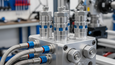
Stacked Valve Architecture: Spools, Checks, Pilots, and Manifold Ports

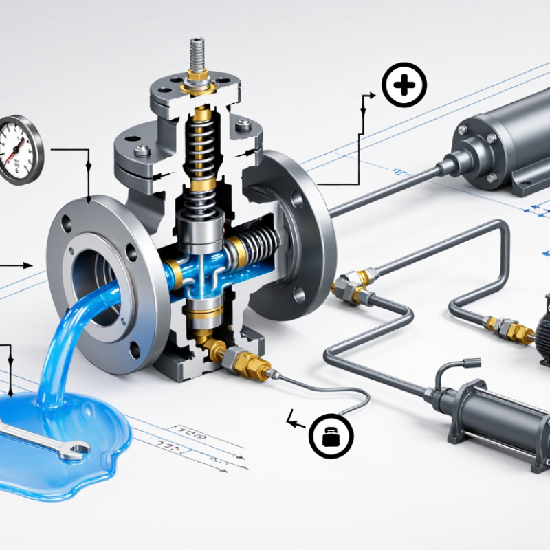
Stacked counterbalance valves combine several hydraulic functions inside a compact manifold. The architecture usually includes a spool, check valve, pilot section, and manifold ports. The check valve allows free flow toward an actuator. The spool then controls return flow from the actuator. During lowering, pilot pressure shifts the spool gradually, preventing sudden load movement. Small pilot changes can create large flow changes. That is the practical detail operators often feel first.

The manifold ports define the circuit’s behavior. Port A may connect to the rod side, while port B serves the opposite chamber. Cross-port pilot lines can balance pressure between two valve sections. A blocked or misidentified port can cause hunting, heat, or delayed release. ISO 4413 emphasizes controlled energy release and contamination management in hydraulic systems. The National Fluid Power Association’s 2024 industry statistics also track shipment indexes rather than simple unit totals, reminding engineers to separate market growth from actual system performance.

Reports from Grand View Research place the global hydraulic equipment market in the tens of billions of dollars, with continued demand for compact control systems. That growth does not make every stacked design efficient. A valve may hold a suspended load securely, yet still waste energy through excessive pilot pressure or restrictive passages. Field testing matters. I would check spool response, pilot pressure, leakage, and temperature under real load cycles. Bench results can look excellent. Machines are less polite.

What Are Stacked Counterbalance Valves and How Do They Work?

Stacked counterbalance valves combine cartridge sections or sandwich modules in a shared manifold. The check section permits low-resistance flow in the lifting direction, while the spring-loaded spool meters controlled lowering. A pilot port applies hydraulic force to reduce the effective opening pressure. Common nominal pilot-ratio options include 3:1, 4.5:1, and 10:1.

Higher pilot ratios require less pilot pressure for the same assisting force, but they can also make the valve more sensitive to pressure changes. Actual settings depend on the actuator load, spring range, port arrangement, spool design, and manifold configuration.

How Load Holding and Meter-Out Control Work in a 3:1 Pilot-Ratio Circuit

Stacked counterbalance valves combine several load-control functions in one compact hydraulic assembly. Each valve holds an actuator when the directional valve returns to neutral. This prevents a suspended load from drifting downward through internal leakage or hose expansion. The valve stays closed until pilot pressure and load pressure create enough force to open it.

In a 3:1 pilot-ratio circuit, pilot pressure acts on an area three times larger than the main poppet area. A relatively small pilot signal can therefore release a much higher load pressure. During lowering, the valve opens gradually and meters oil from the actuator outlet. This meter-out control prevents the load from overrunning the pump flow. It also reduces shock when a cylinder begins moving. Movement should feel controlled, not forced.

Real circuits are less tidy. Backpressure, spring setting, oil viscosity, and trapped air can change the response. I would not select the ratio from a load chart alone. Measure the actual load pressure and confirm the valve setting under operating temperature. A setting that is too low may allow drift. Too high may create heat, chatter, or sluggish motion. In a stacked arrangement, correct porting matters as much as valve adjustment. One reversed section can make a familiar circuit behave strangely. Small details matter.

Sizing by Load Pressure, Flow Rate, and Common 210–350 bar Ratings

Stacked counterbalance valves control overrunning loads in hydraulic cylinders and motors. Each valve holds actuator pressure until pilot pressure permits movement. In a modular stack, several valves share a manifold, reducing hose length and leakage points. ISO 4413:2010 requires hydraulic circuits to manage unexpected movement and stored pressure. That principle matters when selecting a counterbalance valve for cranes, lifts, and mobile equipment.

Sizing starts with load pressure, not valve port size. Calculate pressure from load force and effective cylinder area. Then apply a safety margin without making the setting unnecessarily high. A valve set too low may allow drifting. A valve set too high can generate heat and resist motion. Flow sizing follows actuator speed: Q equals cylinder area multiplied by velocity. The valve’s published flow rating should be checked at its stated pressure drop, not at zero flow. NFPA/T3.6.7 guidance also supports evaluating pressure losses and control stability across operating conditions.

Common pressure ratings include 210, 250, 315, and 350 bar. These values describe working classes, not guaranteed operating limits for every circuit. ISO 4413 and the manufacturer’s technical data must both be reviewed. Field testing often reveals an uncomfortable detail: theoretical sizing can miss hose elasticity, oil temperature, and load shocks. Pilot ratios, commonly around 3:1 to 10:1, strongly influence release pressure and stability. Recheck the selection at minimum and maximum loads. A tidy calculation can still be incomplete.

Installation, Adjustment, and ISO 1219 Hydraulic-Symbol Conventions

Stacked counterbalance valves combine several load-control functions in a compact manifold. They prevent a cylinder or motor from running ahead of its supply flow. This matters when a suspended load could drop suddenly. In field installation, clean oil and correctly capped ports are essential. Even a small particle can affect the poppet or pilot stage.

Mount the valve close to the actuator whenever practical. Keep pilot lines short, protected, and correctly connected. Check the port markings against the hydraulic schematic before tightening fittings. Use a pressure gauge near the controlled port during commissioning. Adjust the relief setting gradually, with the load mechanically supported. Increase pressure only until smooth holding and lowering occur. A setting that is too high can create heat and sluggish motion. I have found that hurried adjustment often hides a piping error.

Under ISO 1219 conventions, hydraulic functions appear inside square boxes. A check valve uses a ball-and-seat style symbol, while a pressure-control element uses a spring and adjustable arrow. Pilot lines are drawn with broken lines, and external drain paths must remain clearly identified. The symbol explains function, not the valve’s physical shape. Therefore, a stacked assembly may appear as separate functional symbols connected by common ports. Port labels still need careful review. Symbols can be read correctly and installed incorrectly. Record the final setting, pilot ratio, and test pressure for reliable maintenance. One practical weakness remains: field conditions rarely match the ideal schematic perfectly. Recheck movement after the system reaches operating temperature.