Choosing Counterbalance Valves is not a simple catalog exercise. The correct choice affects load control, operator safety, energy use, and component life. A valve that looks suitable on paper may chatter when a boom lowers, leak under heat, or respond too slowly beside a heavy excavator arm.
Industry data shows why this decision deserves more attention. Fortune Business Insights valued the global hydraulic equipment market at approximately USD 44.68 billion in 2022. Its report projects continued growth through 2030, driven by construction, agriculture, material handling, and industrial automation. Counterbalance Valves remain a smaller product category within this market, so standalone figures can be difficult to verify. That limitation matters. Buyers should examine technical evidence instead of trusting broad market claims.
Hydraulic specialist Anthony Esposito states, “A counterbalance valve controls an overrunning load and prevents uncontrolled movement.” That principle guides the seven tips in this article. They cover setting pressure, pilot ratios, flow capacity, mounting position, load characteristics, leakage, and supplier documentation. ISO 4413 also stresses safe hydraulic-system design, pressure control, and protection against unexpected motion. In practice, measure the real load first. Check the cylinder area, line length, oil temperature, and maximum descent speed. Small details matter.
There is no universal setting.
A valve selected for a quiet test bench may behave differently on a cold jobsite. This is where experience becomes valuable, although experience alone can mislead. Combine field observations with manufacturer curves, verified calculations, and controlled testing. The best selection is not always the cheapest or largest valve. It is the one that holds the load steadily, releases smoothly, and remains predictable after thousands of cycles.
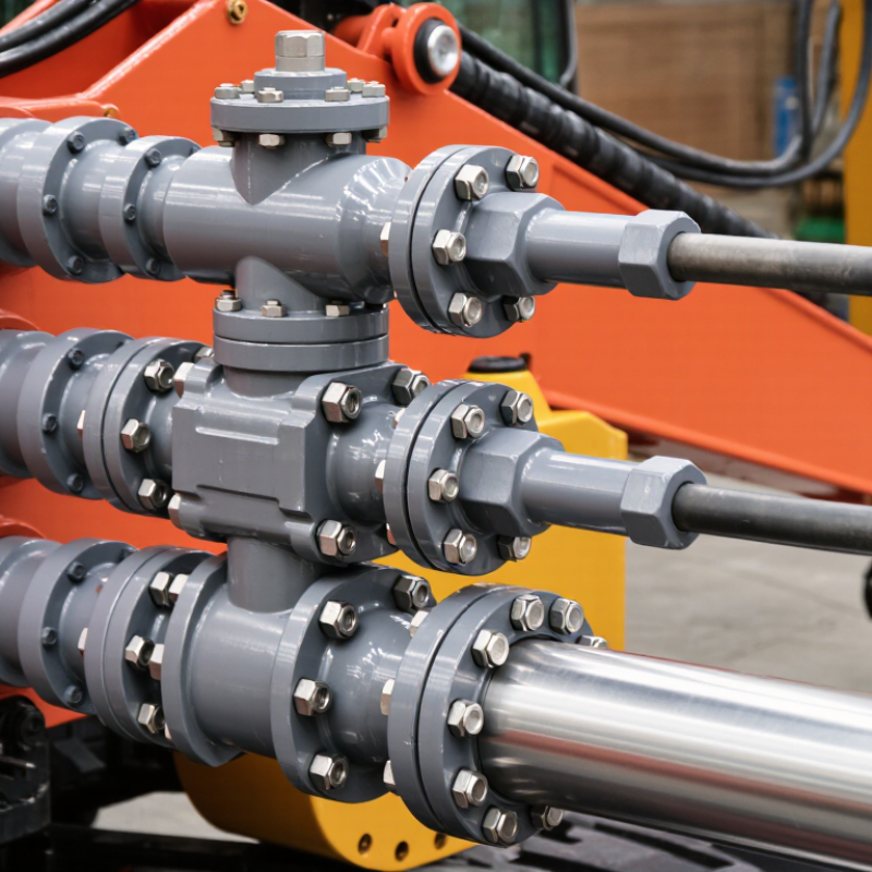
Counterbalance valves control and stabilize hydraulic loads, especially when cylinders or motors move downward. They hold suspended loads when the directional valve is centered. During movement, pilot pressure gradually opens the valve and meters returning oil. This prevents a heavy load from running ahead of the pump. Motion becomes smoother.
Their role is broader than pressure relief. They help prevent load drift, reduce shock, and maintain backpressure during overrunning conditions. A practical inspection starts with the actual load, actuator area, working pressure, and required flow rate. Valve capacity must match the circuit. An undersized valve may create heat and slow movement.
Select a suitable pilot ratio for the load and control response. Excessive pilot sensitivity can cause unstable motion. A low setting may allow the load to creep or fall. Check the pressure setting under real operating conditions, not only on a clean test bench. Temperature changes can alter oil viscosity and response. Contamination can also damage the valve seat.
Install the valve close to the actuator when possible. This arrangement improves load holding if a hose fails. Confirm the correct flow direction and inspect connections for leakage. Test starting, stopping, and emergency lowering several times. Do not treat the valve as a complete safety system; additional protection may be required. Real hydraulic circuits are rarely perfect, so reviewing noise, vibration, and unexpected heat can reveal problems that pressure readings miss.
7 Tips for Choosing Counterbalance Valves
Assessing Load, Pressure, and Flow Requirements
Measure the real load, not only the rated load. Include payload changes, acceleration, gravity, and possible shock. A suspended load can behave differently during startup and stopping. Calculate the required holding pressure from the cylinder area and load force. Then add a sensible safety margin, without creating unnecessary heat.
Check the maximum working pressure and expected pressure spikes. The valve setting should hold the load securely, yet allow controlled movement. Setting it too high may increase energy use and stress seals. Setting it too low can cause drifting or unstable motion. I once treated the pump rating as the actual system pressure. That shortcut was wrong. Pressure gauges at critical ports reveal more useful information.
Match the valve’s flow capacity to the cylinder or motor demand. Excessive restriction can produce sluggish movement and heat. An oversized valve may reduce control sensitivity. Consider the pilot ratio, especially when smooth lowering matters. Lower ratios often improve stability but may require more pilot pressure. Review fluid viscosity, temperature, leakage tolerance, and installation orientation. Confirm the valve works with the actuator’s motion, not just its catalog specifications. Test the machine with a partial load first, then a full load. Record pressure, speed, and temperature during both raising and lowering. Real testing can expose assumptions that calculations miss.
| Tip | Assessment Dimension | Required Data | Practical Calculation or Check | Selection Guidance | Typical Risk if Ignored |
|---|---|---|---|---|---|
| 1 | Determine the load-induced pressure | Load force, actuator effective area, mounting geometry, and whether the load is overrunning | Load-induced pressure = Load force ÷ effective actuator area Example: 20,000 N ÷ 0.002 m² = 10 MPa, or approximately 100 bar |
Choose a valve with a rated working pressure above the maximum calculated pressure, including the machine safety margin | Uncontrolled movement, valve overload, or insufficient load-holding capability |
| 2 | Set the relief or counterbalance pressure correctly | Maximum load-induced pressure, desired holding margin, and circuit pressure limits | A common starting point is a setting of about 1.3 times the maximum load-induced pressure, subject to circuit and manufacturer requirements | For a 100 bar load-induced pressure, an initial setting near 130 bar may be considered if permitted by the system design | Too low: load drift or chatter. Too high: excess heat, higher actuator stress, and inefficient operation |
| 3 | Match the valve flow capacity | Required actuator speed, cylinder displacement, motor displacement, and maximum pump or return flow | Cylinder flow: Q = actuator area × speed Example: 0.002 m² × 0.05 m/s = 0.0001 m³/s = 6 L/min |
Select a valve whose continuous flow rating exceeds the calculated operating flow without excessive pressure drop | Slow movement, overheating, unstable lowering, or excessive pressure loss |
| 4 | Evaluate pilot ratio and pilot pressure | Required lowering pressure, actuator load pressure, pilot supply pressure, and desired motion sensitivity | Higher pilot ratios generally require less pilot pressure to open, while lower ratios can provide greater resistance to unintended movement | Use the pilot ratio specified for the circuit’s load-control and stability requirements; confirm pilot pressure is available throughout the operating cycle | Jerky motion, delayed opening, pilot instability, or failure to release the load |
| 5 | Check dynamic stability and lowering control | Load inertia, speed changes, hose length, line elasticity, valve response, and stopping frequency | Test acceleration, deceleration, stopping, and restart conditions with the highest expected load and speed | Prefer a valve designed for stable metering and smooth load control when the load can overrun the actuator | Oscillation, shock loading, vibration, or unexpected acceleration during lowering |
| 6 | Verify pressure-drop and heat-generation limits | Flow rate, valve pressure-drop curve, operating duty cycle, fluid temperature, and reservoir cooling capacity | Hydraulic power converted to heat is approximately Power (kW) = Pressure drop (bar) × Flow (L/min) ÷ 600 | At 10 bar pressure drop and 20 L/min, heat generation is approximately 0.33 kW; confirm the cooling system can dissipate it | High oil temperature, seal deterioration, reduced viscosity, and shortened component life |
| 7 | Confirm installation, fluid, and safety requirements | Port configuration, mounting location, hydraulic fluid type, contamination level, ambient temperature, and fail-safe needs | Verify pressure rating, temperature range, fluid compatibility, cleanliness requirements, and correct orientation against the technical specification | Install as close as practical to the actuator when hose failure or load drift creates a safety hazard; use additional safety devices where required | Leakage, contamination-related sticking, unsafe load descent, or non-compliance with machine safety requirements |
7 Tips for Choosing Counterbalance Valves
Choosing the Correct Valve Type and Configuration
Choose a direct-acting valve for simple, compact load-holding circuits. Select a pilot-operated valve when smoother lowering matters. Check the load direction before choosing a single or dual valve. A single valve suits one-way overrunning loads. A dual valve protects both actuator ports. Confirm the valve matches the cylinder or motor connection. Small details matter.
Set the pressure rating above the maximum operating pressure, not the average reading. Check flow capacity at the actual working temperature. Specify an internal check valve for controlled free flow into the actuator. Use external pilot control when the circuit needs adjustable or remote pressure management. Review the pilot ratio carefully. A high ratio can reduce required pilot pressure, but it may increase sensitivity. This trade-off is easy to miss.
Mount the valve close to the actuator whenever possible. Long hoses can create delay, vibration, and unstable load movement. Confirm the valve’s mounting position and port orientation before installation. Test lowering speed with the real load, not an empty cylinder. Recheck the setting after warm-up. Oil temperature changes performance. Use a calibrated gauge during adjustment. A neat calculation can still fail in the field. Inspect fittings, seals, and hose ratings together, because the valve is only one part of the safety chain.
The chart compares common counterbalance valve configurations against key selection requirements. Use it as a practical screening guide before confirming pressure, flow, load, pilot-ratio, and installation requirements.
A value of 1 indicates that the configuration is commonly intended to provide the listed function; 0 indicates that the function is not its primary purpose. Pilot-operated valves generally support smoother load control, while dual valves are commonly used when both actuator directions require controlled load holding.
Checking Compatibility with Hydraulic System Components A counterbalance valve must fit the complete hydraulic circuit, not just the actuator. Check port size, pressure rating, flow capacity, and fluid type against the pump, cylinder, motor, hoses, and fittings. A valve rated for 250 bar may perform poorly if nearby hoses are limited to 180 bar. Measure actual load-induced pressure, including shock peaks. Static readings can mislead. Field checks often reveal chatter when warm oil reaches working speed.
Match pilot ratios and control logic with the directional valve and actuator. A pilot-operated valve needs enough signal pressure to open smoothly. Too little pressure can cause drift. Too much may create abrupt movement. Confirm whether the directional valve uses an open-center, closed-center, or load-sensing arrangement. Their interaction matters. Also inspect mounting orientation and adjustment access. A set screw hidden behind a frame is not maintenance-friendly. Leave room for pressure gauges near the valve.
Check contamination tolerance, filtration, sealing materials, and temperature range across every component. Small particles can damage a spool, while incompatible seals may swell after prolonged exposure. Compare the valve’s response time with cylinder speed and motor stopping behavior. Test with real hose lengths and expected loads, not an idealized rig. Test under load. One detail is easy to miss: return-port backpressure. Recheck it during movement, because a cold test may hide a warm-up problem. Record pressure at both work ports and adjust in small steps. A circuit can look correct on paper and still need revision.
7 Tips for Choosing Counterbalance Valves
Evaluating Safety, Maintenance, and Long-Term Performance
Choosing a counterbalance valve should begin with the actual load, not only the catalog rating. Confirm maximum pressure, flow rate, actuator volume, and load direction. A valve with the wrong pilot ratio may cause unstable lowering or delayed movement. Test the circuit under realistic load conditions. Bench data is useful, but field behavior matters more.
Safety depends on controlled motion. Select a valve that limits runaway movement after a hose failure. Check relief settings, mounting position, and compatibility with the actuator. Keep adjustment access clear. Small details matter. During inspection, look for leakage, cracked fittings, damaged hoses, and unusual vibration. A simple inspection record can reveal gradual changes before they become failures.
Maintenance should be practical, not theoretical. Choose seals and materials suited to the fluid, temperature range, and surrounding environment. Contaminated oil can damage internal surfaces and affect response. Install proper filtration and define inspection intervals based on operating hours. Long-term performance also depends on correct installation torque and clean connections. No selection is perfect. I would still review the valve after several months of service, because real loads often differ from the original estimate. A stable valve protects equipment, reduces downtime, and supports safer maintenance work.