Leave Your Message

Top 10 Pipe Counterbalance Valves for Global Buyers?

Choosing reliable Pipe Counterbalance Valves is rarely as simple as comparing pressure ratings. Global buyers must examine load control, leakage performance, response stability, installation space, and service support. A valve that performs smoothly on a test bench may behave differently on a long pipeline, a crane boom, or a mobile machine exposed to cold mornings and vibration.

Andrew Parr, author of Hydraulics and Pneumatics, describes the essential purpose clearly: “A counterbalance valve prevents a load from running away.” That principle remains central when evaluating Pipe Counterbalance Valves for demanding applications. The best option should hold suspended loads safely, open without harsh pressure spikes, and close without causing noticeable chatter. Small details matter. Port size matters. Pilot ratio matters. So does contamination control.

This guide reviews ten Pipe Counterbalance Valves for international buyers. It considers technical performance, material quality, supplier experience, documentation, and practical maintenance needs. The comparison also recognizes regional differences in equipment design and operating conditions. Some valves excel in compact hydraulic circuits. Others suit heavy-duty lifting systems or high-flow industrial pipelines.

No ranking is universally perfect. That needs saying. A valve selected for one machine may disappoint on another. Buyers should verify real operating pressure, load-induced pressure, oil viscosity, and mounting orientation before purchasing. Product pages can look convincing, yet field support may be weak. This overview offers a practical starting point, not a substitute for engineering validation. Expect useful comparisons, but keep room for careful testing.
Top 10 Pipe Counterbalance Valves for Global Buyers?

What Pipe Counterbalance Valves Are and How They Function

What Pipe Counterbalance Valves Are and How They Function

Pipe counterbalance valves control overrunning loads in hydraulic cylinders and motors. They prevent a suspended load from dropping when directional control changes. Inside the valve, a spring-loaded poppet or spool resists downstream flow. Pilot pressure then opens the valve gradually. This action helps maintain backpressure and reduces hydraulic motor runaway. A reverse-flow check path usually allows faster movement in the opposite direction.

Correct sizing requires more than matching pipe diameter. Engineers should calculate load pressure, maximum flow, pilot ratio, cracking pressure, and actuator area. ISO 4413:2010 recommends controlling stored hydraulic energy and preventing unexpected movement. Grand View Research’s 2024 hydraulic equipment analysis forecasts a 4.8% compound annual growth rate through 2030. That expansion increases demand for safer motion control, but it does not make valve selection automatic. A valve that is too restrictive can create heat and slow the machine. A valve set too lightly may permit drift.

Tips: Start with the real load. Check pressure at the port, not only the pump gauge. Inspect hoses, fittings, and mounting position. In field service, technicians often find contaminated oil after unstable motion appears. Filter condition matters. So does pilot-line routing. The perfect setting is rarely practical. Recheck it under cold oil, full load, and emergency stopping conditions. That assumption deserves review.
Key Specifications for Comparing Counterbalance Valve Types

Top 10 Pipe Counterbalance Valves for Global Buyers?

Key Specifications for Comparing Counterbalance Valve Types

Selecting a pipe counterbalance valve requires more than matching port size. Start with rated pressure, maximum flow, pilot ratio, and adjustment range. A valve rated at 350 bar may still perform poorly near its flow limit. Check the pressure drop at the machine’s real operating flow. That figure often exposes hidden heat generation.

Pilot ratio affects load control and stability. Lower ratios usually provide stronger resistance to overrunning loads. Higher ratios can reduce pilot pressure, but may cause sensitive movement or chatter. Compare cracking pressure carefully. A setting that is too high wastes energy; one that is too low may allow cylinder drift. Also inspect internal leakage, response time, temperature range, seal compatibility, and port configuration. ISO 4413 recommends evaluating hydraulic safety, pressure control, and stored energy during system design.

Industry data provides useful context. Grand View Research estimated the global hydraulic equipment market at about USD 49.4 billion in 2023, with continued growth expected through 2030. NFPA’s 2024 U.S. Fluid Power Shipment Statistics also showed ongoing shipment volatility, reminding buyers to avoid assumptions based on market momentum. In field testing, oil cleanliness and installation alignment often matter as much as catalog ratings. I have seen a theoretically suitable valve become unstable after contamination entered the pilot line. That is an uncomfortable detail. Comparing only price and nominal pressure is still common, but it is not a reliable specification strategy.

Top 10 Pipe Counterbalance Valves for Global Buyers

Top 10 Pipe Counterbalance Valves for Global Buyers

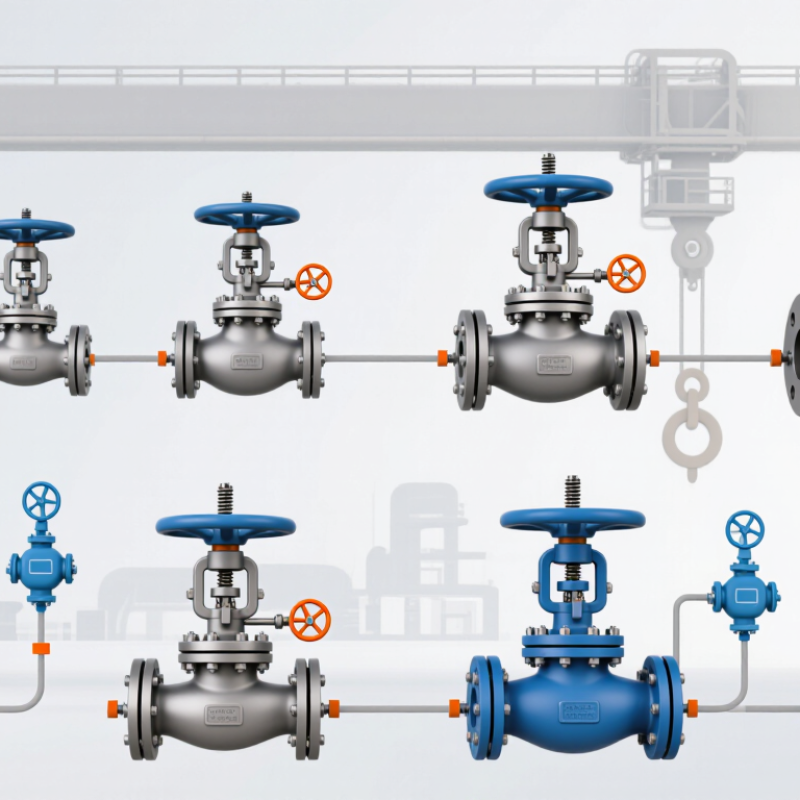
Global buyers often compare ten practical counterbalance valve designs: direct-acting, pilot-operated, single overcenter, dual overcenter, sandwich, cartridge, threaded, flanged, proportional, and load-sensing models. Each design manages suspended loads inside hydraulic piping, but their responses differ. Direct-acting valves suit simple circuits. Pilot-operated versions offer smoother lowering under changing loads. Dual valves help control cylinders in both directions.

Selection should begin with pressure, flow rate, port size, and load weight. Check the valve’s cracking pressure against the cylinder’s actual load, not only the catalog range. A mismatch can cause jerky motion or unwanted drift. Small details matter. Measure the pipe connection carefully. Metric and imperial threads can look deceptively similar. Confirm the fluid type, operating temperature, seal material, and required cleanliness level before ordering.

For international procurement, request pressure-test records, material certificates, installation drawings, and traceable inspection data. Confirm compliance with the destination market’s machinery and hydraulic safety requirements. A reliable supplier should explain pilot ratios, adjustment limits, and emergency lowering behavior clearly. Field inspections often reveal a neglected issue: contamination near the valve can damage seats within weeks. Filtration and flushing deserve equal attention. No ranking fits every system. A high-flow flanged valve may be excessive for a compact machine, while a small threaded model may overheat in continuous service. The final choice should reflect real duty cycles, not marketing language alone.

How to Select a Valve for Pressure, Load, and Fluid Conditions

Top 10 Pipe Counterbalance Valves for Global Buyers

How to Select a Valve for Pressure, Load, and Fluid Conditions

Selecting a pipe counterbalance valve starts with the load, not the catalog number. Calculate the actuator force, movement speed, and maximum working pressure. The valve setting should hold the load securely without creating excessive backpressure. A setting too low may allow drifting. A setting too high can generate heat and waste energy.

Pressure spikes need attention. Check the system’s peak pressure, not only its normal gauge reading. Confirm the valve’s rated pressure, pilot ratio, port size, and adjustment range. A large port does not automatically improve control. Flow paths, hose length, and actuator volume also influence stability. Test the valve under real loading conditions when possible.

Fluid conditions can change the decision. Hydraulic oil viscosity, temperature, cleanliness, and seal compatibility all affect performance. Thick fluid may slow response during cold starts. Contaminated fluid may damage the poppet or restrict the pilot passage. Select materials that suit the fluid and operating temperature. Small details matter.

A neat calculation can still miss field behavior. Mounting position, vibration, and trapped air may produce unexpected movement. During commissioning, record pressure, load response, and temperature at several speeds. Recheck the setting after the system reaches normal operating heat. The first adjustment is rarely perfect.

Top 10 Pipe Counterbalance Valve Profiles for Global Buyers

Typical maximum working-pressure requirements by application. Use pressure, suspended-load behavior, pilot ratio, and hydraulic-fluid compatibility together when selecting a valve.

The values represent common hydraulic design requirements for these equipment categories, not brand performance rankings. Final selection should be verified against the valve datasheet, peak pressure, load-induced overrunning conditions, oil viscosity, temperature, and applicable safety standards.

Installation, Maintenance, Safety, and International Compliance

Top 10 Pipe Counterbalance Valves for Global Buyers: Installation, Maintenance, Safety, and International Compliance

A counterbalance valve must sit close to the actuator, reducing hose-burst risk and uncontrolled load movement. Keep pipe runs short and support them against vibration. Confirm the valve’s flow direction, pilot ratio, pressure rating, and fluid compatibility before installation. A clean hydraulic system matters. ISO 4406 cleanliness targets should guide filtration and sampling, although many buyers treat them as optional.

Set pressure only after measuring the real load-induced pressure. Avoid copying factory settings blindly. Improper adjustment can create heat, chatter, or load drift. Inspect fittings, seals, mounting bolts, and emergency holding performance during scheduled maintenance. Lockout procedures should follow OSHA 29 CFR 1910.147 or the applicable national equivalent. The U.S. Bureau of Labor Statistics recorded 5,283 fatal workplace injuries in 2023, showing why stored hydraulic energy deserves serious control.

ISO 4413 supports safe hydraulic-system design, while ISO 12100 provides a structured machinery risk-assessment method. For European projects, buyers should also review the Machinery Regulation (EU) 2023/1230 and the Pressure Equipment Directive where applicable. CE documentation, technical files, declarations, and local importer duties may differ by product classification. International compliance is not a sticker. It is traceable evidence. One uncomfortable lesson remains: perfect paperwork cannot rescue poor installation. A valve can meet every listed standard and still fail when contamination, temperature, or operator training is ignored.

Top 10 Pipe Counterbalance Valves for Global Buyers? - Installation, Maintenance, Safety, and International Compliance
No. Generic Valve Configuration Typical Port Size Typical Flow Capacity Typical Maximum Working Pressure Common Pilot Ratio Typical Adjustment Range Recommended Installation Fluid and Temperature Maintenance Guidance Primary Safety Considerations Relevant International References
1 Direct-acting pipe-mounted counterbalance valve G 1/4 to G 1/2; NPT 1/4 to 1/2 10–40 L/min 250 bar 3:1 35–250 bar Install close to the actuator port, with the load-holding side connected directly to the actuator. Mineral hydraulic oil; typically −20 to +80 °C Check for leakage and pressure drift during commissioning; inspect the spring and poppet every 12 months or 2,000 operating hours. Not a substitute for a mechanical load-support device when personnel may be exposed to a suspended load. ISO 4413; ISO 12100; ISO 4406 cleanliness control
2 Pilot-operated pipe counterbalance valve G 1/2 to G 1; NPT 1/2 to 1 30–120 L/min 315 bar 4:1 70–315 bar Mount in the actuator line with the pilot connection routed to the opposite pressure line and protected from contamination. Mineral hydraulic oil; typically −20 to +80 °C Verify pilot-line restriction, check valve operation, and setting stability at scheduled service intervals. Use a calibrated pressure gauge and prevent pilot-line blockage, which can cause uncontrolled deceleration or load movement. ISO 4413; ISO 12100; ISO 13849-1 where integrated into a safety-related control system
3 Dual counterbalance valve for double-acting cylinders G 1/4 to G 3/4; SAE and metric options 20–100 L/min 315 bar 4:1 or 8:1 50–315 bar Install as close as practical to both cylinder ports to reduce hose-burst and hose-expansion risks. Mineral hydraulic oil or approved biodegradable fluid; typically −20 to +80 °C Inspect both pressure settings, seals, fittings, and hose connections; retest after any actuator or hose replacement. Both load directions must be evaluated; unequal settings can cause drift, vibration, or unexpected movement. ISO 4413; ISO 12100; ISO 6020/2 or ISO 6022 for applicable hydraulic cylinders
4 Flange-mounted high-flow counterbalance valve SAE 3/4 to SAE 1 1/2; ISO flange patterns 80–300 L/min 350 bar 3:1 or 4:1 100–350 bar Use rigid, correctly aligned pipework and torque flange bolts according to the applicable flange standard. Mineral hydraulic oil; typically −20 to +80 °C Inspect flange seals, bolt torque, external leakage, and pressure response at least annually. Support heavy valves and piping independently; do not use the valve body as a structural pipe support. ISO 4413; ISO 6162 for applicable flange interfaces; ISO 12100
5 Sandwich or stack-mounted counterbalance valve NG 4 to NG 10 valve interface 25–160 L/min 315 bar 4:1 50–315 bar Install between compatible manifold sections and verify port alignment, tie-rod length, and stack torque. Mineral hydraulic oil; typically −20 to +80 °C Check interface seals and manifold fasteners; clean valve plates before reassembly to avoid internal contamination. Confirm that the complete stack pressure rating is not lower than the individual valve rating. ISO 4413; ISO 4401 for applicable mounting interfaces; ISO 12100
6 Counterbalance valve with integrated anti-cavitation check valve G 1/2 to G 1; SAE 8 to SAE 16 30–150 L/min 315 bar 4:1 or 10:1 70–315 bar Fit near the actuator and ensure the make-up check valve receives clean oil from a sufficiently sized return line. Mineral hydraulic oil; typically −20 to +80 °C Monitor for cavitation noise, inspect the check-valve seat, and verify return-line back pressure. Excessive return pressure can alter the effective counterbalance setting and increase actuator heating. ISO 4413; ISO 4406; ISO 12100
7 Electrically adjustable proportional counterbalance valve G 1/2 to G 3/4; SAE 8 to SAE 12 20–100 L/min 315 bar 4:1 50–315 bar, control-dependent Install with a stable electrical supply, correctly shielded control wiring, and a manual override or fail-safe strategy where required. Mineral hydraulic oil; typically −20 to +70 °C; coil temperature limits apply Calibrate command-to-pressure response, inspect connectors, and verify the fail-safe position during planned shutdown tests. Loss of power or signal must be assessed; electronic control does not automatically provide a safety-rated load-holding function. ISO 4413; IEC 60204-1 for machinery electrical equipment; ISO 13849-1 where applicable
8 Anti-shock and counterbalance combination valve G 3/4 to G 1 1/4; SAE 12 to SAE 20 60–220 L/min 350 bar 3:1 or 4:1 100–350 bar Connect the valve to the actuator line with short, adequately rated hoses and provide access for pressure adjustment. Mineral hydraulic oil; typically −20 to +80 °C Check the counterbalance and relief settings separately; inspect for pressure spikes after load changes. The relief function must be sized for the actual trapped volume, actuator area, and maximum permitted load speed. ISO 4413; ISO 12100; ISO 13849-1 when used within a safety control architecture
9 High-temperature pipe counterbalance valve G 1/2 to G 1; SAE 8 to SAE 16 25–120 L/min 250 bar 4:1 50–250 bar Provide thermal isolation where necessary and keep the valve away from exhaust manifolds, furnaces, and direct radiant heat. High-temperature hydraulic fluid; commonly −10 to +120 °C, subject to seal selection Shorten inspection intervals, check seal hardness and leakage, and confirm fluid viscosity remains within the valve operating range. Temperature changes affect viscosity, cracking pressure, seal life, and pressure stability; validate the complete temperature envelope. ISO 4413; ISO 12100; applicable fluid and elastomer compatibility requirements
10 Corrosion-resistant stainless-steel pipe counterbalance valve G 1/4 to G 3/4; NPT and metric options 10–100 L/min 250 bar 3:1 or 4:1 35–250 bar Use compatible stainless fittings, prevent galvanic corrosion, and protect the adjustment mechanism from salt spray or chemical exposure. Mineral oil or compatible water-glycol fluid; typically −20 to +80 °C Rinse external deposits, inspect fittings and seals, and retest pressure settings after corrosion or chemical exposure. Material resistance does not guarantee resistance to every process chemical; confirm compatibility with the actual environment. ISO 4413; ISO 12100; ISO 9227 for applicable corrosion testing; ISO 4406
Representative generic specifications are provided for international comparison and preliminary selection. Actual pressure, flow, temperature, port, seal, and compliance ratings must be confirmed against the final valve datasheet and the applicable local machinery, pressure-equipment, electrical, and import requirements.