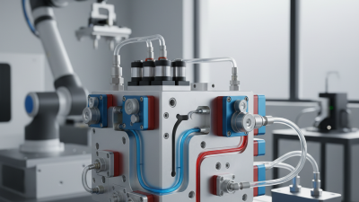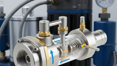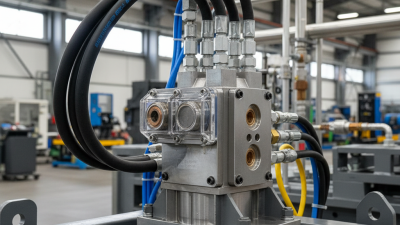
Hydraulic lift systems depend on controlled oil flow, stable pressure, and dependable valve response. The Hydraulic Lift Valve Manifold brings these functions together in a compact assembly. Its passages, seals, and valve interfaces can affect lifting smoothness, heat, leakage risk, and service time. Small details matter.
Grand View Research estimated the global hydraulic equipment market at USD 44.6 billion in 2023, with projected growth through 2030. This broad market estimate is useful context, but it does not measure lift valve manifolds alone. That distinction matters. Buyers should compare suppliers on the evidence they provide, not on market growth claims.
This guide examines suppliers through practical criteria: operating-pressure range, flow capacity, materials, machining quality, testing procedures, customization, and after-sales support. For example, a manifold serving a warehouse lift may face different duty cycles and space constraints from one used in mobile equipment. Ask for pressure-test records, dimensional drawings, compatible-fluid guidance, and traceable product specifications. Not every catalog agrees. That can slow evaluation, and it deserves attention.
A polished brochure is not proof of field reliability. Supplier claims should be checked against documented test methods and relevant hydraulic-system requirements, including ISO 4413 where applicable. This overview is a starting point, not a substitute for engineering review. The right choice depends on the application, installation conditions, and maintenance plan.
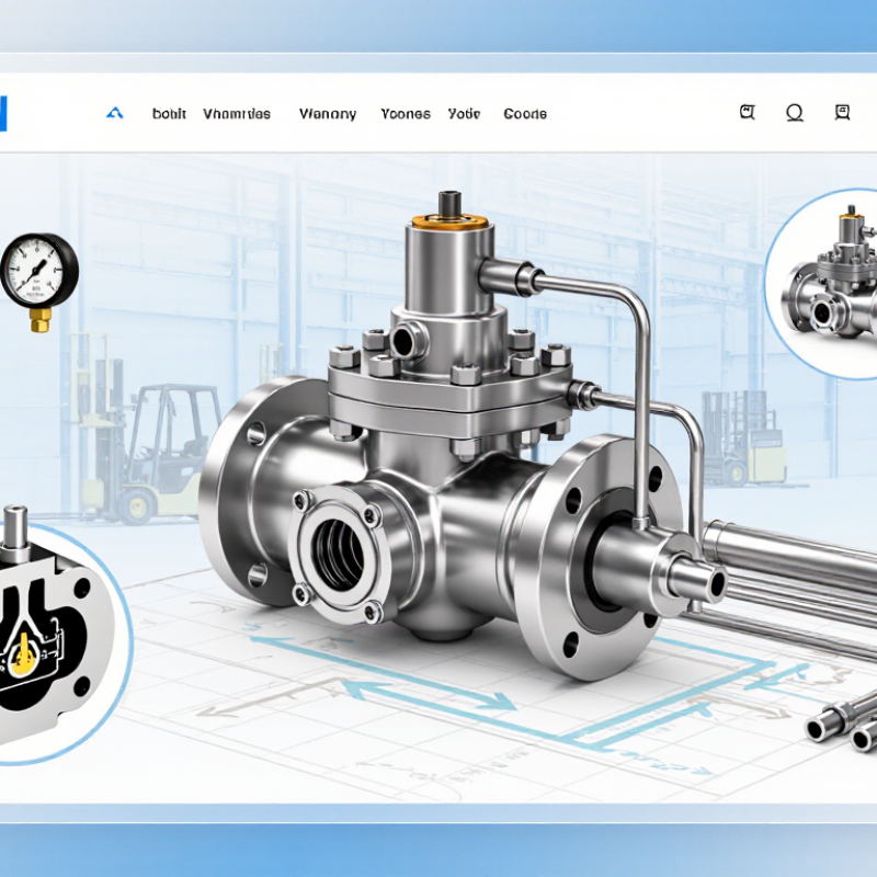
A hydraulic lift valve manifold directs oil between the pump, reservoir, and lift cylinder. It also houses valves that control direction, pressure, and load movement. In a typical circuit, P receives pump flow, T returns oil to the tank, and A and B connect to actuator lines. Port labels can vary, so check the machine schematic before connecting hoses.
During raising, the directional valve routes pressurized oil toward the cylinder. A check valve may hold the load when the control returns to neutral. During lowering, oil leaves the cylinder through a controlled path, often regulated by a counterbalance or flow-control valve. The setting matters: a heavy platform can descend abruptly if return flow is poorly controlled. Small details count.
When inspecting a manifold, look for clear port markings, secure fittings, and signs of leakage around plugs and valve cartridges. Match the manifold’s pressure and flow ratings to the system, not just the lift’s appearance. A narrow passage can create heat and slow movement. Manifold sizing is sometimes treated as a quick selection, but that deserves a second look; cylinder area, pump output, and load behavior all affect performance. Even a sound layout may need testing under real operating conditions.
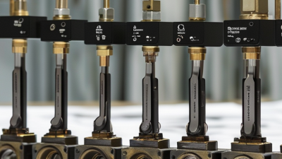
Top Hydraulic Lift Valve Manifold Suppliers?
Pressure ratings need context. ISO 4413:2010, the hydraulic fluid power safety standard, requires components to suit foreseeable operating conditions. It does not provide one universal working-pressure rating for every manifold. Buyers should compare a supplier’s continuous working-pressure rating with measured circuit peaks, including pressure spikes during starts, stops, and sudden load changes.
Ask for the manifold’s pressure-test report. Check the test pressure, duration, fluid temperature, test medium, and acceptance criteria. A proof-test value is not a continuous operating rating. Neither is a burst-pressure figure. Small distinction. Big consequence. Compare the circuit’s documented peak pressure with the component’s allowable rating, and have an engineer set an appropriate margin for the application. Do not rely on a rounded catalogue maximum.
Request pressure-cycle data for the specified manifold configuration, including port sizes and valve arrangement. A report for a similar unit may not represent the assembly being purchased. Check that fittings, seals, and connected valves have compatible pressure ratings, too. One gap often remains: test reports may omit transient conditions. Ask how those conditions were measured, and record the answer before approving a supplier.
How to use this table: These are buyer-defined screening tiers for comparing supplier offers, not supplier-specific product ratings and not pressure limits prescribed by ISO 4413. Obtain and verify the actual manifold rating and supporting documentation for the exact configuration, fluid, temperature, and duty cycle.
| Anonymous manifold duty profile | Buyer screening pressure tier | Pressure rating evidence to request | ISO 4413-aligned safety checks | Comparison decision |
|---|---|---|---|---|
| Compact lift circuit; moderate load and duty | 160 bar (16 MPa) minimum declared working-pressure target | Manufacturer’s rated working pressure for the complete manifold assembly; confirm the rating applies to every pressure-containing section and port. | Check that component ratings suit the maximum system pressure, that pressure cannot exceed the weakest component’s rating, and that the circuit has suitable pressure-limiting protection. | Advance only if the documented rating meets the system design pressure and the supplier identifies any operating or temperature limits. |
| General-purpose lift circuit; higher load or frequent cycling | 210 bar (21 MPa) minimum declared working-pressure target | Request the rated working pressure, allowable pressure peaks or transients, and the conditions under which those values apply. | Assess pressure surges, load-holding and lowering functions, and the consequences of component or hose failure. Confirm pressure protection is appropriate to the circuit design. | Compare the declared rating with both normal operating pressure and foreseeable transient pressure; do not treat a peak rating as a continuous rating. |
| Heavy-duty lift circuit; elevated pressure requirement | 250 bar (25 MPa) minimum declared working-pressure target | Obtain ratings for the manifold body, valves, seals, plugs, fittings, and interfaces as installed; request written confirmation of the assembled configuration’s limits. | Verify pressure-containing parts are suitable for the intended pressure and operating conditions, and that the design addresses leakage, unintended movement, and safe pressure release during service. | Reject offers that provide only a valve or material rating without confirming the assembled manifold’s applicable pressure limit. |
| Special high-pressure lift circuit; application-specific design review | 315 bar (31.5 MPa) minimum declared working-pressure target | Require configuration-specific datasheets and written confirmation of working pressure, transient limits, fluid compatibility, temperature range, and any derating. | Complete a documented risk assessment for the full hydraulic system. Confirm pressure limitation, isolation and depressurization provisions, and safe maintenance procedures for stored hydraulic energy. | Use only where the full system design supports this tier; a higher pressure rating alone does not establish system safety or suitability. |
| Any lift circuit with unknown or changing pressure conditions | Set the target only after measuring or calculating maximum operating and transient pressures | Request the supplier’s rating basis and identify test conditions, temperature limits, permitted fluid, and exclusions. Confirm applicable ratings for all connected components. | Apply ISO 4413 safety principles to the complete system: assess foreseeable hazards, prevent pressure from exceeding component limits, and provide suitable controls for safe operation and maintenance. | Do not rank suppliers on nominal pressure alone; compare documented ratings against the application’s verified design conditions. |
Top Hydraulic Lift Valve Manifold Suppliers?
When comparing hydraulic lift valve manifold suppliers, ask how they specify fluid cleanliness. ISO 4406 reports particle counts at three sizes: 4, 6, and 14 micrometres. Its code helps teams compare oil samples consistently. Lower code numbers indicate fewer particles in the measured size ranges.
Cleanliness needs depend on valve design, operating pressure, and component clearances. A manifold with tight spool clearances may react poorly to fine debris. Ask suppliers for a recommended ISO 4406 target and the test method behind it. Then check whether the target fits your pump, filters, and maintenance routine. One sample is not the whole story. Sampling from a stagnant line can give a misleading result, so follow a repeatable procedure and record operating conditions. In practice, even careful maintenance can miss a source of contamination.
Tips: Compare the same particle-size ranges and sampling conditions. Check filter ratings, but do not treat them as proof of clean oil. Review trends over time; a rising code deserves investigation, even if the lift still operates normally.
ISO 4406 codes describe particle concentration in hydraulic fluid. This chart shows the upper particle-count limit for each code band.
How to use this: An ISO 4406 result is a three-part code for particles ≥4, ≥6, and ≥14 µm(c) per millilitre—for example, 18/16/13. Lower code numbers indicate cleaner fluid. The chart gives the upper concentration boundary for an individual code band; it is a reference, not a universal cleanliness requirement for every valve manifold. Confirm the target with the component or equipment specification and operating conditions.
When comparing hydraulic lift valve manifold suppliers, request a legible schematic that identifies every valve and connection. Check its symbols against ISO 1219, which provides standard graphical representations for fluid power systems. The drawing should show flow paths, ports, actuation methods, and spring-return positions. Small details matter. A missing port label can make a correct-looking circuit difficult to verify.
Trace the circuit in each operating state. For example, follow oil from the pump through the directional valve to the lift cylinder, then check the return path to tank. Confirm that check valves, relief valves, and load-holding components appear in the right locations. Do not guess. A symbol shows function, not the manifold’s physical layout, so match schematic port labels with the block markings and connection list. Ask for clarification when these documents disagree.
A careful supplier should provide consistent, revision-controlled drawings and explain any application-specific symbols. Compare the schematic with the valve list and test documentation before approving a design. ISO 1219 alignment improves communication, but it does not prove correct sizing, safe operation, or performance under load. That distinction is easy to overlook. Even a tidy drawing may leave questions about pressure settings or energized valve states, so record those details and resolve uncertainties before installation.
Top Hydraulic Lift Valve Manifold Suppliers?
Rank suppliers by documented performance, not polished catalogues. Put testing first: request pressure-test records, leakage limits, cleanliness controls, and traceable inspection results for the exact manifold configuration. ISO 4413:2010 sets safety requirements for hydraulic systems, making documented design reviews and risk controls meaningful checks. A test certificate without clear acceptance limits tells you little. Look closely.
Customization ranks next. Compare each supplier’s ability to adapt port locations, valve combinations, mounting patterns, and flow requirements against your drawings. Ask for a marked-up drawing before production, plus a sample change-control record. Deloitte and MAPI’s 2023 Smart Manufacturing Survey found that 86% of manufacturing executives expect smart manufacturing to drive competitiveness within five years. That finding supports traceable digital records, but it does not prove a supplier can machine a reliable block.
For delivery, score suppliers using their actual on-time shipment rate over the past year, not a promised lead time. Confirm how they handle delayed castings, revised drawings, and urgent replacement parts. After-sales support deserves its own score: measure response times, troubleshooting quality, spare-part availability, and access to engineering staff. A simple ranking might weight testing at 35%, customization at 25%, delivery at 20%, and support at 20%. Adjust those weights for your operating risks. A spreadsheet cannot reveal every shop-floor habit; visit the facility when possible.